The Basics Of PLC Programming – Part 4
In this installment of our ongoing Practicing PLC Technician Series, we will expand on our knowledge of the virtual counterparts to real world field equipment already familiar to PLC technicians working in industry today. The last physical device we will be examining is the counter. We will take a brief look at how the virtual version of this device is implemented when programming modern day PLCs to perform industrial control applications. We will also illustrate how a technician can become familiar with the wide variety of additional instructions used with the AB SLC 500 series of controllers.
What is the difference between the CTU and CTD counter instructions?
When programming PLCs, we encounter 2 basic types of counters, an UP counter or CTU instruction, and a DOWN counter or CTD instruction. As you may have intuited, CTU counter instructions start at a user defined value (stored in the ACC or accumulated field of the instruction),and count up or increment the value each time a “false to true transition” occurs on the rung on which the instruction is located. The CTD instruction is used to decrement a user defined (again a value stored in the ACC field for the instruction) value each time the rung on which this instruction is located exhibits a “false to true” transition. In both instances, a field device such as a special purpose sensor, physical wand, or a proximity detector causes an input rack location to change states. Information pertaining to these counter instructions is stored in the C5 (counter) data file location. In addition to the individual counter types, (up or down counter), it is possible to combine these instructions to create a counter bi-directional counter or “counter pair”.
How do you create an UP/DOWN counter pair?
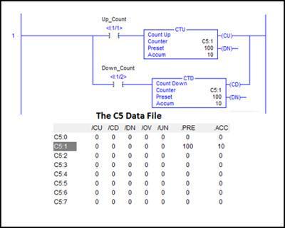
In addition to the preset and accumulated value fields previously mentioned, status bits and the counter reference can be shared by these two counter types. The memory location structure of the C5 file provides storage for user defined values as well as status bits as we learned in our introductory articles on Data File types and structures.

In the above illustration, the “Counter” field for both the CTU and CTD instructions reference the same memory storage location, C5:1 (also shown in the figure). Each memory location in that file stores the CU (up count enabled), CD (down count enabled), DN (done), OV (overflow), UN (underflow) status bits as well as the Preset and Accumulated value for counters that share the C5 reference. In this example, the Preset value is set to 100. Notice that value is shared and displayed as the Preset value for both counters. The current Accumulated value is 10 and it is also shared and displayed in each instruction. When the I:1/1 contact closes, the CTU counter is triggered. This will increment the Accumulated value stored in the C5:1 memory location and the modified value will be displayed in both instructions. When the I:1/2 contact closes, the Accumulated value will be decremented and will return to the value of 10. Each of the existing counters is capable of modifying this Accumulated value. They also share bit status. In this way, a running count can be incremented or decremented by field events (state transitions at the I:1 input module referenced by the contacts on the rung.
The video below illustrates the behavior of an up/down counter pair employed to keep a running count value that can be incremented or decremented as required. The video outlines an elevator hoist routine that uses a running count to track the elevator car location.
Is sharing a data file storage address among multiple instructions a common thing?
There are other instructions capable of employing a shared memory location reference. Another common instruction that employs the use of this reference sharing technique would be the SQO sequencer output instruction. It is possible to have several of these sequencer instructions all sharing the same R6 control data file memory location, while referencing different Source file locations. The objective in this instance would be the sharing of the POS (position) value. This would move the file pointer in each of the referenced source files in step with each other. Technicians would use this facility to create a virtual Sequencer Table and send parts of the table data to different output or instruction field locations. A sequencer table could store the output pattern for the lights in a traffic light application.
A separate sequencer table could store the timing information for each step in the light sequence. As the pointers move together, each output light pattern (being sent to the output locations controlling the lights) is stepped through, the corresponding time duration for each step can be sent to the Preset field of a timer instruction.
How do you research the behavior of the wide variety of instructions available with SLC 500 series controllers?
The basic extended instruction set is detailed in the vendors User’s Instruction Set Reference Manual. The guide lists the available instructions, and describes the operation and data associated with each instruction. As the instructions are too numerous to be expounded upon in this format, it is important to familiarize yourself with this resource.
In our next installment, we will list a few of the most common programming errors associated with the instructions we have covered in this blog series and how to avoid them.
If you like this post, check out our other posts in the Practicing PLC Technician Series.
We hope that this has been helpful as a student or practicing PLC technician. We are looking for other ideas for the Practicing PLC Technician Series. Please let us know if you have any ideas that you would like to see and send your thoughts to support@gbctechtraining.com
