The Basics of PLC Programming - Part 2
In our last installment of the Practicing PLC Technician Series, we began to look at some of the similarities between relay logic control circuits and plc ladder logic programming. Over the next few blogs, we will further examine some additional instructions that are based on real world field equipment or devices that have been included in the ladder logic programming approach available for programming modern PLC’s.
The Basics Of PLC Programming – Part 2
Application control programs generally consist of 2 types of routine segments; time driven segments and event driven segments that generally either direct a series of timed events, or provide a desired response to changing conditions in the environment. In addition to these two basic routine segment types, programs often also include a means of repeating routine segments a desired number of times. In this installment, we examine Time Driven routine segments with a simple practical everyday example.
What’s an Example of a Time Driven Routine Segment?
Time driven routines employ timer instructions (TON and TOF as well as RET) to perform timed tasks. Timers can be run concurrently to address different aspects of a single task, or can be cascaded to perform a sequence of timed events. Timers are versatile, and are widely employed in PLC programming applications. An everyday example of a timed routine segment can be seen in the control of an elevator door. The elevator door opens, the doors remain open for a period, and then the elevator door closes. Each part of this door sequence is being performed for a specified time duration. This is accomplished by using timer instructions in conjunction with the appropriate outputs for door motor control. In addition to the cascaded timer type applications, another common timer application is a reciprocal timer. In that instance 2 timers work together to provide an ON and OFF timing duration.
The ON duration timer is used to start the OFF duration timer. The OFF duration timer is used to reset the ON duration timer and restart the cycle. This type of application can be used for something as simple as flashing lights.
How Do Timer Instructions Work?
The T4 Timer data file is used to store information on timer instructions being used in a given ladder logic control application. The most common timing instruction is the “on-delay” (TON) timer. For a more detailed review visit our blog File Based Addressing with respect to the T4 Timer File.
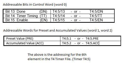
As a quick visual review, here is the T4 timer file data structure for a single timing instruction. We recall that this structure consists of 3 Words of 16 bits length each. This allows for the storage of timers bit status, (DN, TT, EN) as well as the “Preset” and “Accumulated” time values.

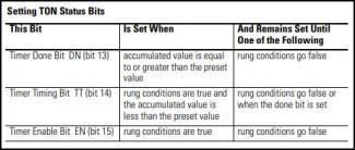
The TON delay timer instruction has 3 useful status bits, the enable (EN), timer timing (TT), and done (DN) bits. These are the primary bits used to drive timed routine segments. Below, find the basic operation of this type of timing instruction explained as well as how the status bits respond during operation. This TON instruction can be used to turn on or off an output after a given period of time has expired. The instruction counts time base intervals ( 0.1s) when the rung condition it is on becomes TRUE. As long as the rung condition remains true, the timer modifies its accumulated value (ACC) time each iteration until it reaches the preset value (PRE). The accumulated value gets reset when the rung condition goes false regardless of whether the timer has timed out or not. The status but behaviour is as follows:

In addition to the TON delay timer instruction, two other timer instructions are included in the basic instruction set. The TOF delay timer, and the RET or retention timer. The retention timer functions much the same way as the TON delay timer with a couple exceptions. The Accumulated value is not reset when the rung condition goes false, it is kept. This allows the time interval to be interrupted, and then resumed without losing the current time value. The other significant difference with this instruction is that it requires a reset (RES) instruction to clear its accumulated value.
This video animation reviews an example of using cascading timers to make an elevator door routine in ladder logic as described in the article above. This video provides an excellent example of the instructions we have covered to date, namely, coils, contacts, and timers and provides an illustration of cascading timers to perform a cyclic operation such as opening and closing elevator doors.
In the next installment of the Practicing PLC Technician series, we will take a look at the virtual version of another control device used in PLC ladder logic programming and familiar to technicians, the sequencer. This instruction will be used in an example of a basic event driven routine segment.
If you like this post, check out our other posts in the Practicing PLC Technician Series.
We hope that this has been helpful as a student or practicing PLC technician. We are looking for other ideas for the Practicing PLC Technician Series. Please let us know if you have any ideas that you would like to see and send your thoughts to support@gbctechtraining.com
