5 Tips on How to Reduce Scan Time Using Ladder Logic - Part 1
In the next two blogs, we will discuss scan time and its impact on everyday PLC applications as well as examine how it can be reduced. Scan time is an important metric to be considered in many high-speed PLC applications. The time it takes to perform a single scan cycle can have significant impact on the input stimulus and/or output control signals present or required for high-speed applications. Specialty I/O modules are often employed in these situations and offer significant advantages. That said, it is important to note that scan cycle time can also be of significance for general applications as well. Although they may not have the extreme constraints and dependencies of high-speed applications, general applications, such as a simple multiplexing program segment, can have practical limitations that can relate directly to scan time. The impact scan time has on the operation of timers can be significant. It is generally accepted that an understanding of the impact of scan time along with some basic knowledge of how it can be reduced is important when learning how to program a PLC with ladder logic.
We will examine a simple example of each of the following 5 tips over the next two blogs:
1. Place instructions/conditions that are most likely to be false at the start of a rung to reduce the number of instructions seen during the scan.
2. Avoid duplicating unique tag/instruction combinations when creating ladder logic programs whenever possible. A change in architecture can often reduce the total number of instructions used in a program reducing memory usage as well as scan time.
3. Program flow control can be key to significant reductions in scan time. Use the JMP and LBL instructions to reduce the active segments of a running program.
4. Compartmentalizing tasks (making modular processes) and organizing them can have significant impact on scan time. Passing variables can allow for program segments (subroutines) to be used in multiple instances.
5. Avoid floating point arithmetic and try to use integers wherever possible. If you need better than integer precision, consider multiplying all your floats by 10, 100, or 1000 to get integers.
A basic example of each scan cycle time reduction tip:
Let’s review a simple example of each the first two tips.
1. The instruction most likely to be false should be at the start of a rung.
When possible, arranging instructions from left to right with the likelihood of them being false determining their position is a good practice that should be adopted. Consider the simple motor seal-in rung below:
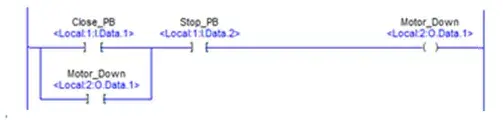
The “Stop PB” pushbutton field device is a normally closed momentary contact switch. When the application is running, the normally open contact associated with it closes due to the state of the pushbutton in the field. For this reason, the branch part of the seal in, should appear to the left of the “Stop PB” pushbutton contact on the rung. The Stop PB contact will be closed most of the time during program execution. It should not be the first instruction scanned on the rung. This small effect can have a significant impact on scan cycle time cumulatively.
2. Avoiding the duplication of unique tag/instruction combinations.
Consider this program segment that is used to provide a single start/stop station using a momentary contact pushbutton.
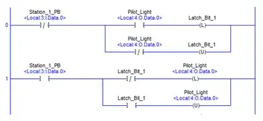
The program segment above is optimized and does not use any unique tag/instruction combinations more than once. If the application called for the use of a second station, one could copy this structure and modify the tags to create the program segment shown below:
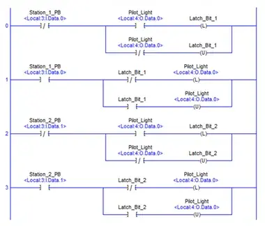
Although this was an easy way to accomplish our objective, we have introduced a duplication of 4 tag/instruction combinations. The XIO, XIC, OTL and OTU instructions are appearing twice with the “Pilot_Light” alias tag in the version above. The impact of this redundancy would increase for each additional station that may be required. An alternate topology can be the way to resolve this redundancy issue.
The program segment shown below will function identically to the version having 2 stop/start stations we examined previously.
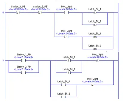
This version of the program segment uses 4 instructions less than the previous version. It contains no duplicate tag/instruction combinations and this new topology is easy to expand upon when additional stations may be required. It was not immediately apparent that there was another way to organize the required logic for this example, but time should be taken for the attempt as it is always worth the effort when successful and can have a significant impact on scan cycle time as well as memory usage.
In our Part 2, we will examine the remaining three tips to minimize PLC scan cycle time with ladder logic programming and provide examples of each case. These last three tips we will look at are often considered to have the most significant impact on scan cycle times, so be sure and check back with us for our next installment.
We hope that this has been helpful as a student or practicing PLC technician. If you have any questions regarding the PLC Technician program, feel free to get in touch with us at [email protected] or give us a call at 1-888-553-5333 to speak with a Program Consultant.