File Based Addressing Tips - Part I
This is the first in a series of brief articles discussing important topics specific to PLC (Programmable Logic Controller) technicians and technician students preparing for a role in an increasingly automated workforce. In this series we will be discussing skills and knowledge unique to the understanding of PLC’s. It is our intention to offer insight to those individuals who perform everyday general technician level tasks. The role of PLC technicians in today’s workforce is expanding. The need to have a basic understanding of PLC programming is becoming more and more significant for the PLC technicians of today. For this reason, topics of discussion in this series will focus primarily on providing a general understanding of basic PLC programming and the various instructions available for use with 16 bit controllers. We will be examining some of the skills that are required, in addition to basic electrical knowledge, with an emphasis on understanding existing 16 bit PLC operation and programming. This generation of controller is currently being employed in a wide variety of existing industrial and manufacturing applications.
I would recommend that our readers also check out our series for Practicing Electronics Technicians for valuable tips on the electrical and electromechanical aspects relating to common tasks for PLC technicians. Those articles provide general circuit analysis tips as well as tips on other related topics. We do not want to downplay the significance of having a solid understanding of the traditional skills employed by PLC technicians. Our intention is to assist the technician in expanding on the skills that are increasingly significant in today’s technician workforce. These helpful articles can be found at: Tips for Practicing Electronics Technicians
What is “File Based Addressing”?
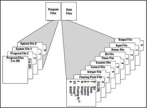
Today’s topic is the first in a two part article that provides an introductory understanding of the “File Based Addressing” scheme used with 16 bit (500 series) PLC’s from Allen Bradley. Although addressing schemes are proprietary in nature, Allen Bradley’s approach can serve as a valid representation of the addressing schemes generally employed by this generation of controller, and the principals set out in this article can be easily applied to 16 bit controllers offered by a host of other vendor’s. PLC memory allocation consists of 2 general areas: program files, and data files. Each section consists of 256 files, some of which are predefined, while others are flexible and can be used to suit the needs of a given application. The part of the file based addressing scheme that will be discussed in this article, resides within the 256 files contained in the Data Files section of PLC memory. Files 0 through 8 in the data files section are standard and predefined as shown in the figure below. Files 9 through 255 can consist of any of the available file types depending on the user’s needs. The figure below lists the 11 basic data file types, Output, Input, Status, Bit, Timer, Counter, Control, Integer, Floating point, String, and ASCII. These files store data and values pertaining to I/O, instructions, processor status, as well as variables in data tables. All of these file types can be referenced using the File Based Addressing scheme.
Memory File Organization For The File Based Addressing System
What is an Address?
An “address” is essentially a means of referencing a location in memory. Addresses allow for physical I/O as well as the data or status of instructions/elements to be accessed by the controller. These values are stored in the Data Files portion of the PLCs memory. The Data File section of memory is organized into 11 general file types. Each file type is denoted by a specific letter which is used at the start of all associated addressing.
What is I/O addressing?
The most familiar addresses encountered by technicians would be those addresses pertaining to physical I/O locations. The state of physical connection points on the I/O rack will be stored in the “I” and “O” files in the PLCs memory. The format for an I/O address will start with the file type, (I or O), followed by its slot number in the I/O rack, It will end with a reference to the specific terminal number (0-15) on the module of interest.
An input address related to terminal connection 12 on an input module situated in slot 3 of the I/O rack would have the address I:3/12 This address contains 3 alpha numeric characters and 2 delimiters. The address starts with the memory file type “I” denoting its location in the input file. The next item in the address is the delimiter “:”. This delimiter is used to separate the file type from the slot number containing the input module that is being referenced, in this instance slot 3. After the slot number is specified, a second delimiter (a backslash), separates the slot number from the actual terminal connection point (0-15) on the input module. The state of this terminal connection point, (high or low in the case of discrete I/O) will be stored in the input file. A 16 bit word, stored in the input file, is used to represent each one of the input modules present in the I/O rack. Each terminal, on a given module, is represented by a single bit in that 16 bit word. Bits 0 through 15 in the stored word correspond to terminals 0 through 15 on the input module. The values appearing at these terminals (high or low for discrete modules) will be stored to the corresponding memory location in the “I” (input) File.
An output address follows the same format as an input address. It consists of 3 alpha numeric values and 2 delimiters. Data pertaining to output addresses are stored in the “O” File. A discrete output can be turned on or off by storing a high or low value to a memory location associated with a specific terminal in a specific I/O rack slot location. As an example, if you wish to turn on a device connected to terminal 7 of the output module located in slot 2 of the I/O rack, you would store a 1 value to the address O:2/7. Once again, the “O” (output) File is organized into a data table of 16 bit words. Each terminal on the output module corresponds to a single bit in a given word. Each output module in the rack will correspond to a separate word in the data table contained in the file. Module terminals will present the state (high or low for discrete I/O) that has been stored to the corresponding “O” (output) File in memory.
In addition to addresses referencing physical terminals in the I/O rack, it is common to reference “Virtual Outputs” using this addressing scheme. A virtual output is an output that does not physically exist in the I/O rack. For instance, if 8 slots in the rack are populated with modules of various types, a virtual output can be referenced by specifying a slot number that is not present or in use. The address O:10/0 is an example. Since there is no slot 10 in the rack, there is no module associated with this address. This does not mean, however, that there is not a word “10” in the data table in the “O” (output) File. Virtual outputs can be used as internal memory locations to store status or data without referencing an actual terminal on an output module.
What other things can be referenced by this addressing scheme?
In addition to I/O addressing, data tables containing variables/values can also be referenced using addresses. There are 3 types of values that can be stored in the file based addressing system, Integers, floating point values, and single bit values. These values are stored in the “N” (integer) File, “F” (floating point) File and the “B” (binary/bit) File types. Each of these files are organized into a table of “words”. Each word and/or bit in these tables can be referenced individually using this addressing scheme. In part two of this article we will examine the addressing format for these 3 files, as well as examine some specialty files that store custom data structures used to hold information pertaining to timers, counters, and control elements. These addresses as well as the structure of the associated timer (T), counter (C) and control (R) files are a bit more involved than the straight forward I/O addressing we have examined so far. We have obtained a solid basic knowledge of the general file organization that should serve to assist in understanding the File Based Addressing system as we move forward. In addition, we have examined the most basic form, namely, discrete I/O addressing. We will build on this in the second part of this article which will appear in the next installment in the series.
We hope that this has been helpful as a student or practicing PLC technician. We are looking for other ideas for the Practicing PLC Technician Series. Please let us know if you have any ideas that you would like to see and send your thoughts to [email protected].