GBC Updates its PLC Technician Certificate Curriculum
In keeping with GBC’s longstanding tradition of garnering student and industry feedback, we are happy to announce that we have updated our PLC Technician Certificate program curriculum to include new features and content directly in response to industry needs and our students most prevalent requests. The program content update includes additional information on “program flow control related” items such as “Interrupts” and their usage, as well as content relating to closed loop control systems, specifically the PID instruction and how it is used.
The PLCLogix 500 simulation tool has also been updated to include another 3Dworld emulating Valves and new instructions relating to the additional information now included in the program content. The use of the PLCLogix 500 simulation tool plays an integral part in reinforcing and digesting the concepts discussed in the program content. Having working interrupts, interrupt zone control, and a PID instruction allows students to explore and experiment with these new concepts.
In addition, monitoring and graphing of analog data relevant to conditions within the 3D environments has been added to help with student comprehension.
What’s been added to Module 10 “Program Flow Control”? Interrupts.
Module 10 content has been expanded to include a new section discussing interrupts. Examples,
illustrating the usage of each type of interrupt, are provided for clarification. Interrupts are used in PLC applications to address unexpected or undesirable conditions or events. They can be used to protect equipment, trigger alarms, suspend operations, as well as suspend regular program execution to perform specific tasks at regular timed intervals. There are four general interrupt types and they are addressed in the order provided in the list outlined below:
1. Fault Routine Interrupts
These deal with events/issues classified as minor and major faults caused by everything from hardware-related problems such as equipment failure to software-related issues including programming errors.
2. Discrete Input Interrupts
Often used in applications where high-speed counters are required. This function allows the processor to execute a subroutine when the input of a discrete I/O card matches a programmed compare value.
3. Selectable Timed Interrupts -
Can suspend the scan of the main program file, on a periodic basis, in order to execute a specified subroutine file. Once the subroutine has been executed, the program resumes from where it was interrupted.
4. I/O Interrupts
Often used by specialty I/O modules to interrupt the normal processor operating cycle in order to scan a specified subroutine file. Not all specialty I/O modules are capable of generating these I/O interrupts. The cards that do, generally relate to high speed counting or motion.
What’s been added to Module 14 “Process Control”? PID instruction.
A new section has been added to module 14 that illustrates the usage of the PID instruction and what the key parameters are. PID control is commonly used in manufacturing processes to control position, temperature, pressure, flow rate, etc. A PID instruction uses an algorithm to correct the error between a measured process variable (PV) and a desired setpoint (SP) by calculating and then outputting a corrective action that can adjust the process quickly to keep the error to a minimum. The PID instruction controls the process by sending output signals to actuators which control physical properties and/or equipment. It allows the user to implement the mathematical functions of a PID loop by setting certain parameters and does not require extensive knowledge of algorithms and equations which are usually needed for tuning PID loops. These processes are important to understand as a control system technician, engineer or PLC programmer.
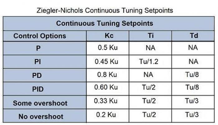
The steps for tuning a PID loop using the Ziegler-Nichols method with the PID instruction are also discussed in the new section:
1. Set the loop to manual mode (Word 0, Bit 1).
2. Turn off integral and derivative action and set proportional gain to a small value.
3. Change the value of the operating SP. An offset or error should be noticed between SP and PV.
4. Place the controller in automatic mode (Word 0, Bit 1)
5. Increase PV by 10% step increases until a continuous and sustained oscillation occurs.
That is, the amplitude of the oscillation must be neither increasing nor decreasing.
It may be necessary to make changes in the setpoint to induce oscillation.
6. Record this value of gain as the ultimate gain, Ku
7. Record the resulting period as the ultimate period, Tu. This period is the time
(in seconds) for it to complete one cycle of oscillation. (inverse of the un-damped natural frequency)
8. Calculate the tuning parameters Kc (controller gain), Ti (integral time), and Td (derivative time) for the PID controller using the Ku (ultimate gain) and Tu (ultimate period) values found above with the factors displayed in the table shown here:
This new information on this tuning approach can now be used with the PID instruction and the analog I/O functionality added to the Batch Mixer, the Single Compressor, and the new Valve Control 3D Worlds in the PLCLogix 500 simulation software. The simulation tool has been updated to provide new instructions and environments for use with interrupts and closed loop PID control applications.
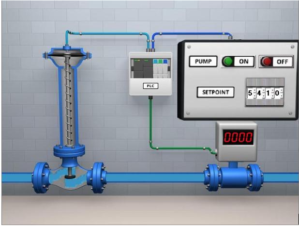
What’s been added to the PLCLogix 500 Simulation Software? Valve 3DWorld.
Here is a list of the instructions that have been added to the instruction set with this latest update:
STE - scalable timed enable instruction
STD - scalable timed disable instruction
STS - selectable timed start instruction
IIE - I/O interrupt enable instruction
IID - I/O interrupt disable instruction
RPI - reset pending interrupt
PID - closed loop PID control block instruction
The tab for the S2 file setup allows the user to setup and define the use of the STI (selectable timed interrupt) and the DII (discrete input interrupt) operations. These new instructions and functionality support the content additions discussed earlier above. The ability to create examples and test the behaviour of applications using the PLCLogix 500 virtual simulation environments plays a key role in student comprehension and material retention. The addition of interrupt functionality as well as having a working PID instruction constitutes a significant enhancement to the overall simulation functionality and usability.
A new 3D environment has been added that focuses on operation of a valve control system along with alternate versions of 2 previously available applications, the single compressor and batch mixer 3D worlds. In these alternate versions, as well as the new Valve positioning environment, analog control of valve positioning, temperature, and tank level control is now possible.
Another addition to the simulation tool is the TREND function (accessed from the controller tree) allows the user to define variables, addresses, or instruction element parameters to monitor in real time during simulation. The user is provided with the instantaneous numerical value present at the specified memory location along with its historical minimum and maximum values. The specified memory locations data also gets plotted graphically over time for review and analysis. Targeted groups of file addresses or instruction parameters can be referenced and monitored easily with this new feature.
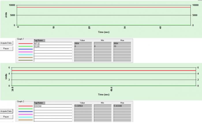
In the above, we are monitoring a Setpoint value and a discrete input in the upper Graph 1, and the output control signal to the valve in the lower Graph 2. Each graph section is capable of monitoring and plotting 7 variables and being viewed in real time while the simulation is running.
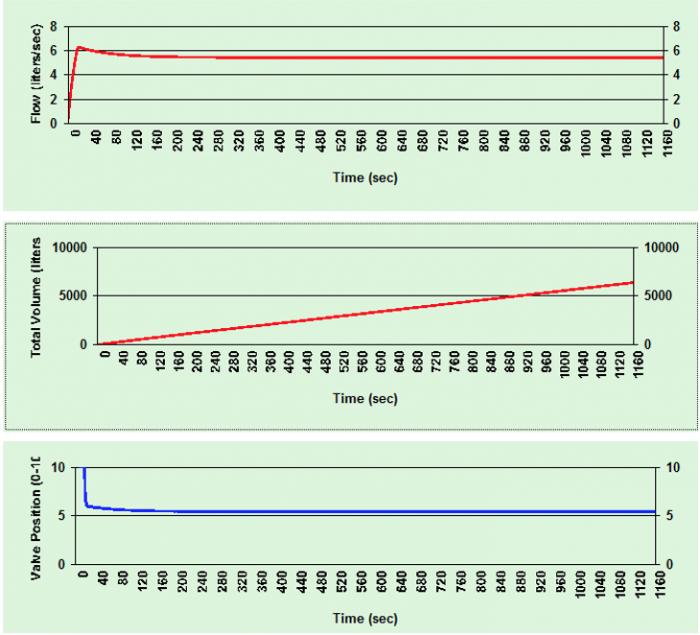
External data is also being plotted with the 3D environments that utilize the I:7 and O:8 analog I/O modules. This data lends insight into the control or behaviour of devices/elements within the environment. Examples of the king of additional plotted data include motor RPM, flow dynamics along with other application specific data that is relevant to a specific application. In the Valve application, parameters such as Total Volume, Flow Rate, and Valve Position can be plotted in real time as shown in the example below.
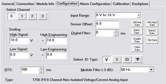
This additional environment “device/element” data can be accessed by clicking on the appropriate buttons in the setup tabs for the I:7 and O:8 four channel analog I/O modules. These 7 data buttons appear on the right side of both the I:7 and O:8 modules dialog box as shown in the example below:
This new functionality, data tracking tools, and analog I/O utilization in the 3D application environments, when combined, constitute a significant improvement to overall topic coverage and serves as our direct response to our students requests and suggestions on how to improve the PLC Technician Certificate Program. We will continue to collect data from students and industry partners and update our programs with that feedback in mind.
To view a short, animated video illustrating the new updates to the PLC Technician Certificate content as well as additions to the PLCLogix 500 Simulation Software, click on the video embedded below.
If you have any questions regarding the PLC Technician program, feel free to get in touch with us at [email protected] or give us a call at 1-888-553-5333 to speak with a Program Consultant.