Standard Practices And Errors Encountered By Beginners When PLC Programming - Part 1
Over these next two installments of our ongoing Practicing PLC Technician Series we will examine some common programming concepts as well as some of the most common programming errors that occur when utilizing the instructions we have covered in basic control applications. To date we have taken a look at coils, contacts, sequencers, timers, and counters, as well as the file structure used to store instruction information, status bits, and program variables. These elements combined provide us with the basic concepts needed to begin programming simple control applications. This installment will focus on five basic common practices.
What are some commonly used approaches?
When programming PLCs, although each control environment/application may be specific and specialized, there are some concepts that are generally adopted/used with a wide variety of applications. In Part 1 of our discussion, we will take a look at the following common practices:
- Using basic combinational logic to control outputs
- Using field closures
- Using a “Seal-In” for the “Start/Stop” station
- Using a virtual “Control Relay”
- Using an “Interlock” for mutual exclusivity
1. Using basic combinational logic to control outputs
As we have seen in our discussion on coils and contacts, an output device can be controlled by a coil instruction that references the output rack location (physical address) that the device is connected to. To turn the field device on, you simply energize the coil that references that specific output rack location address. In the majority of cases, outputs will need to be turned on or off depending on a set of defined conditions or criteria specific to the given control application. These conditions can be defined using contacts associated with input rack locations or instruction status bits. Review the ladder logic program below containing three rungs. This simple program illustrates the use of some of the basic logic functions implemented in ladder logic form.
Basic Logic Functions (AND, OR, NOT)
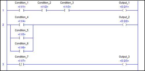
Rung 1: The Logical AND Function
This rung controls the Output 1 coil connected to output rack location O:2/1. The device connected to this output will be turned on or off depending on the state of this output coil. The configuration and type of contacts in rung 1 create the AND logic function. This means that Condition 1 AND Condition 2 AND Condition 3 must all be HIGH at the input locations (I:1/1, I:1/2, I:1/3) in order to continuity to exist on this rung. When continuity exists on rung 1, the Output 1 coil will be energized
Rung 2: The Logical OR Function
This rung contains what is referred to as a “Branch”. It controls the Output 2 coil connected to output rack location O:2/2. In order for continuity to exist on this rung, Condition 4 OR Condition 5 OR Condition 6 must be HIGH at the input rack locations referenced. (I:1/4, I:1/5, I:1/6) If any ONE of these input rack locations is HIGH, the Output 2 coil will be energized and a device connected to the O:2/2 output rack location will be turned on.
Rung 3: The Logical NOT Function
This rung consists of a single normally closed contact in line with the Output 3 coil that controls output rack location O:2/3. In this instance, Output 3 will be energized when Condition 7 is NOT occurring in the field. This means that the device connected to output will be on as long as there is NOT a HIGH at input rack location I:1/7.
2. Using field closures
The term “field closure” refers to using an input device, such as a momentary contact switch that is normally closed (NC), with a normally open (NO) contact associated with the input location that the switch is connected to. The program will contain a normally open contact that remains open when the program is offline. As soon as the program is placed in the RUN mode however, the HIGH state created by the closed momentary contact switch is recognized at the input rack location, and the normally open contact closes immediately.
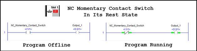
As can be seen above, the field device provides a HIGH at the input terminal, and this HIGH state closes the NO contact in the program. The input device does not need to be a switch, it can be any device that provides a HIGH at the input rack when in its rest state.
3. Using a “Seal-In” for the “Start/Stop” station
It is a standard practice to use a “seal in” rung and a control relay for applications containing a Start/Stop station. A majority of control applications will use an NC momentary contact switch for the Stop button The Stop button will control an NO contact in the program. They will generally employ the field closure technique described above. The Start button in most applications will be an NO momentary contact switch controlling an NO contact in the program. Due to the momentary nature of this type of switch we will need a means of maintaining continuity on the rung when the Start push button switch is released. To accomplish this task,, a virtual control relay is used with an NO contact in parallel with the Start button as illustrated below:
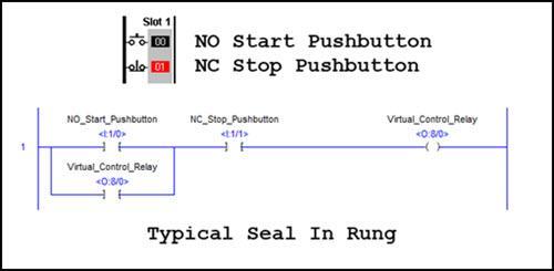
Let us take a moment to examine the construction and operation of the program rung shown above. In addition to contacts referencing the two types of pushbutton switches (Start and Stop) connected to Slot 1 of the input rack, we also have an output coil. This output coil is a “virtual” output as its reference does not correspond to a physical output rack location. This Virtual Control Relay references a memory location that will be used to store the state of the coil in the O8 Output File. An NO contact referencing this virtual control relay coil is placed in parallel with the momentary contact Start pushbutton. This contact will respond to the state of the virtual relay coil stored in the output file location (O8 output file, word 0). When this coil is energized, (by the pressing of the Start pushbutton) the contact in parallel with the Start pushbutton is closed. This means that even after the Start pushbutton is released and its associated NO contact opens again, continuity will persist on this rung. The only way to interrupt continuity is by pressing the NC Stop pushbutton. That will de-energize the virtual control relay and open the contact associated with it. When the Stop pushbutton is released, even though its associated contact would close, the path around the Start contact is no longer available and continuity is interrupted until the Start pushbutton is pressed once again.
4. Using a virtual control relay
A Seal-In rung is only one of the uses for employing a virtual control relay coil in an application. This item is also used as a general safety feature in programming.
The figure below shows the same Start/Stop seal in rung in a simple motor control application. In this program, the motor can be started or stopped using the external Start, and Stop momentary contact switches. In addition to using the virtual control relay to provide continuity around the Start switch contact which will re-open once the Start pushbutton is released, this control relay coil is used to create, or break, continuity on the rung containing the Motor output coil and the rung containing the “Running” indicator output coil.
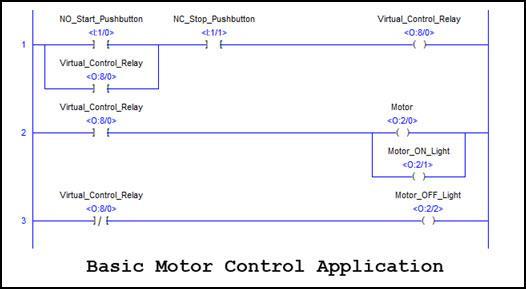
In the application above, in addition to creating the seal in discussed in the previous section, the control relay is used to make or break continuity on the Motor control rung as well as the rung controlling the Idle indicator. Prior to the Start pushbutton being pressed, the Control Relay coil is de-energized and continuity exists on rung 3. That rung contains a NC contact that remains closed as long as the control relay coil is de-energized. When the Start pushbutton is pressed, the control relay is energized, and in addition to the contact in the seal in rung the NO contact on rung 2 closes and both the Motor output (O:2/0), and the Motor ON Light output (O:2/1) are energized. At the same time, the NC contact associated with the control relay on rung 3 opens and the Motor Off Light output (O:2/2) is de-energized.
It is a standard practice to employ contacts associated with a control relay on rungs that have output (OTE) instructions that reference actual physical output locations. This ensures that even if other conditions on the rung containing an output instruction referencing a physical field device are true, the output device can be shut down by de-energizing the control relay coil. In fact, all output devices can be shut down using a single control relay coil and multiple NO contacts.
5. Using an “Interlock” to achieve mutual exclusivity
Mutual exclusivity between two outputs is achieved by ensuring that only one of the two outputs can be energized at any given time. They can never be on together.
This is often desirable in cases where equipment can be damaged or conditions can become dangerous when outputs that should never be energized together are turned on at the same time. In the field this is done by physical device safety equipment. In a PLC program, we use an Interlock configuration. This programming feature ensures the desired restrictions for the outputs of concern. It basically calls for placing an NC contact associated with the first output in line with the second output, and inversely, placing an NC contact associated with the second output in line with the first output. In this way, continuity cannot exist one both rungs of the ladder logic program at the same time.
You can review a video animation outlining how a programmed interlock is used to ensure that two door motor control outputs (one to open and the other to close the door) are mutually exclusive and cannot be energized at the same time. Click on the link below to view a tutorial on creating such an interlock.
In the second installment on standard practices and frequent errors for beginners, we will switch gears and cover some of the most common programming errors associated with the instructions we have covered in this blog series and offer some pointers on how to avoid each of them.
If you like this post, check out our other posts in the Practicing PLC Technician Series.
We hope that this has been helpful as a student or practicing PLC technician. We are looking for other ideas for the Practicing PLC Technician Series. Please let us know if you have any ideas that you would like to see and send your thoughts to [email protected]