What Are the Different Types of PLC Programming Languages
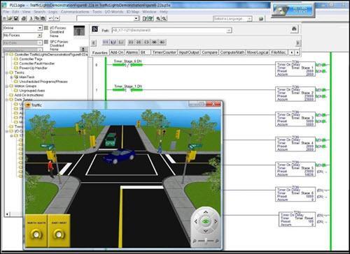
Programmable Logic Controllers (PLCs) are general-purpose control devices often used in plants or manufacturing systems. They provide both a useful and efficient control solution for a variety of applications, and can accept inputs from a variety of devices, such as motion detectors, joysticks and buttons, amongst others. In turn, PLCs are able to produce outputs that control lights, motors and sound effects, amongst others. Programming resources for this input-output system can include timers, counters and other variables.
While PLCs can be very effective in their commercial applications, they come with a steep learning curve. There is some difficulty in learning their functionality as well as inherent difficulty with program maintenance using their traditional Relay Ladder Logic (RLL) programming language. It should also be noted that PLCs from different manufacturers can be programmed in various ways.
If you’re an aspiring PLC technician, or considering enrolling in an online PLC training course, there are three primary PLC programming languages of which you should be aware.
Function Block Diagram
Function Block Diagram (FBD) is the fundamental language for all PLC programmers. It’s relatively simple in nature and programs functions together within a PLC program graphically.As its name would suggest, FBD allows a PLC technician to put functions written with lines of code into boxes, or blocks.
You can then connect these boxes to create the larger PLC program. Almost all PLC programs are written, at least partially, with FBD, because it offers the technician the ability to connect various functions together. The function blocks are integral to this programming language, as they delineate the relationship between input and output functions.
Within the FBD language, there are a few standard blocks. Amongst the most important ones include:
-
Bit Logic Function Blocks
-
Bistable Function Blocks
-
Edge Detection
-
Timer Function Blocks
-
Counter-Function Blocks
There is an infinite number of function blocks provided within a FBD, and oftentimes, one exists for almost every operation that can be performed within PLC programming, including:
Arithmetic Function Blocks;
-
Bit Shift Function Blocks;
-
Character String Function Blocks;
-
Conversion Function Blocks;
-
Communication Function Blocks
Additionally, many PLC technicians and enthusiasts will often build their own function blocks.
Ladder Diagram
Also called Ladder Logic, Ladder Diagram (LD) is a visual PLC programming language, which one can learn fairly quickly. Those with experience with electric relay circuits may find LD programs relatively easy to grasp, as the two look very similar. The organization, PLCOpen, has established the standards for LD making it one of the only standardized PLC programming languages. Essentially, each function is coded into a rung and once many rungs join together in a program, they make what looks like a ladder.
LD was created for technicians and electricians who have a background reading and understanding electrical circuit schematics. Rather than using text, LD programming uses graphic elements called symbols, which have been made to look like electrical symbols. An important difference, however, is that while electric circuits are drawn horizontally, LD programs are created vertically.
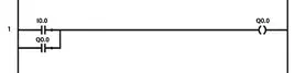
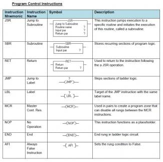
As you construct the LD program vertically, the PLC will execute one rung (or symbol) at a time, as each symbol in the ladder is an instruction. When you create a new piece of ladder logic, you will notice two vertical lines, and it’s in between these two lines where you’re ladder logic will live. You’ll proceed to draw vertical connections between the original lines, creating the rungs of information. You can then proceed to include any of the aforementioned symbols within these rungs, forming the instructions for the PLC. Executing the program one rung at a time, the PLC will typically scan all of its inputs and then proceed to execute the program to set outputs. A few common symbols, or instructions, include:
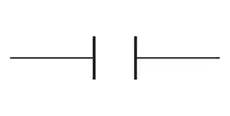
Examine If Closed: looks like two short vertical lines parallel to one another with the name “I0.0” found above the symbol. This is a conditional instruction and is often used to check whether or not something is true, for example, it can check if a bit is turned on. When the PLC checks the state of its inputs, it will assign a boolean value in its memory (either 1 or 0). If an input is low, the bit will be set to 0, alternatively, if an input is high, the bit will be set to 1.
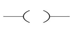
Output Coil: looks like a set of parentheses and is used to turn a bit on and off.
Output Latch: allows you to direct the PLC to perform a continuous output even if the digital input is, let’s say, a momentary pushbutton (that is, a device that needs to constantly be pushed down to work). This is especially handy, for example, when dealing with a fan for a ventilation system where it would be inconvenient for the operator to continuously hold down the fan’s button.
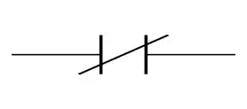
Examine If Open: is another symbol with the memory address “I0.1.” This function looks like the Examine If Closed symbol, but with a diagonal line crossed through the two vertical lines, and works in the exact opposite way of Examine If Closed.
There are a number of other symbols involved in LD programs, a few of which include:
Structured Text
The Structured Text (ST) programming language is text-based and is often regarded as one of the easiest languages to understand for beginners and for those building programs that will be read by others. While graphics-based programs, such as the aforementioned FBD or LD, may seem easier to decipher, using a text-based language (such as ST) will take up less space and allow users to more easily follow the logic of the program. Another benefit of ST is that it can be combined with different programming languages. For example, you can create function blocks containing functions written in ST, and because ST is a standardized programming language you can proceed to program different PLC brands with it.
Similar to ladder logic, programs written in ST are executed one line at a time. The basic syntax of ST revolves around “Program” and “End_Program” which sandwich your PLC program, as seen below:
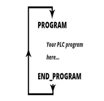
It’s important to note that the “End_Program” command will not end your program definitively, but rather instruct the PLC scan cycle to start over again causing your program to repeat itself.
Your PLC programming software will likely implement the “Program”/”End_Program” construct automatically, prompting you to write the code needed to fill the construct. While there are many syntax details that govern ST, there are some general rules of which you should always be mindful:
All statements are divided by semi-colons;
-
ST is not case-sensitive: while it’s good practice to use sentence-case for readability, it’s not necessary
-
Spaces have no function: similar to using sentence-case, using spaces improve readability.
Depending on their manufacturer, PLCs use a wide array of different programming languages. In much the same way humans around the world speak in different languages and dialects, so too do PLCs with the same end goal: to communicate with each other and execute functions.
In our PLC Technician program, we introduce you to all of these PLC programming languages while focusing on Ladder Logic. If you want to learn what else we teach in our online program, check out our curriculum.