The Basics of Ladder Logic
One of the top 5 most popular types of PLC programming languages is ladder logic. But what makes it so popular, and what does it take to master the language? Ladder logic is a programming language and one of the first languages that was ever used for PLCs or programmable logic controllers.
If you’re interested in working with PLCs, then you have to know the basics of ladder logic and how important it is to these machines. Learning ladder logic is basically like learning a new language, but thankfully, if you already have some working knowledge of PLCs, you’ll catch on quickly. In this article, we will discuss the history of ladder logic, why it’s popular, ladder programming, and ladder logic basics.
The History of Ladder Logic
To understand the history of ladder logic, let’s begin with a definition of process control. Process control is commonly understood as a discipline that uses industrial control systems to achieve consistency and safety during production that could not be achieved manually by humans alone.
Ladder logic began as a method to document the design and construction of relay racks as used in manufacturing and process control. Relay racks are storage systems that are used for networking and communications equipment, and were popularly used prior to the 2000s. They were numbered in some fashion, usually top to bottom and left to right like spreadsheet cells.
Each device would be represented by a symbol with their corresponding devices. External devices would also be shown on the diagram, such as pumps and heaters. However, relays were expensive and they often failed quickly as the mechanical parts wore out and the electricity used burned away the parts. With the advent of PLCs, it was essential to keep similar systems in place, thus ladder logic evolved to become the first PLC programming language.
Why is Ladder Logic Popular?
Ladder logic is the most popular method of PLC programming because it is a graphics based programming language and mimics relay logic. Engineers, electricians and students that are already familiar with relay logic found it easy to transition from an electric circuit to ladder logic, compared to other text based programming languages.
Ladder logic was designed to have the same look as electrical ladder diagrams, but instead, the physical contacts and coils are replaced with memory pieces. When programming ladder logic in a PLC, the graphic, drag and drop nature of ladder diagrams helps create code quickly. Ladder logic also helps troubleshoot code because visually, the flow of logic from the LHS start rail can be seen through the logic symbols and to the RHS end rail.
The Key Components
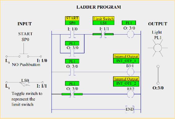
As with computers, PLCs operate with binary signals, using 1 or 0 - this type of data is called a boolean. When implementing a ladder logic program in a PLC there are seven basic components that are important to know:
Rails: vertical lines running down the far most ends of the page. If they were in a relay logic circuit they would represent the active and zero volt connections of the power supply where the power flow goes from the left hand side to the right hand side.
Rungs: horizontal lines that connect the rails to the logic expressions. If they were in a relay logic circuit they would represent the wires that connect the power supply to the switching and relay components. Each rung is numbered in ascending sequential order.
Inputs: the inputs are external control actions such as a push button being pressed or a limit switch being triggered.
Outputs: the outputs are external devices that being are turned on and off such as an electric motor
Logic Expressions: used in combination with the inputs and outputs to formulate the desired control operations.
Address Notation/Tag Names: the address notation describes the input, output and logic expression memory addressing structure of the PLC. The tag names are the descriptions allocated to the addresses.
Comments: comments are displayed at the start of each rung and are used to describe the logical expressions and control operations that the rung, or groups of rungs, are executing.
To execute ladder logic, the PLCs central processing unit (CPU) will read the physical units tied to the input and output modules, updating their status in the CPU’s memory. The CPU then works its way down the ladder, executing each rung from left to right. Once the CPU reaches the last rung, it will update the real outputs and then loop back around and start over again.
You Can Master Ladder Logic
Because ladder logic is the most popular programming language used for PLCs, it’s integral to learn if you’re interested in working with them. Ladder programming is a visual language, and because it mimics electrical relay circuits, most people find it easy to learn ladder logic basics.
The Programmable Logic Controllers Technician (PLC) certificate program is uniquely positioned to provide training and educational insights for individuals interested in working with PLCs across industries. Contact us for more details about the program and how you can register.
Comments
PLC Technician II
Submitted by Persoff Bonner on Mon, 01/24/2022 - 02:12
I'm interested in becoming certified in this area.
PLC technician training
Submitted by Ibrahim Abubak… on Thu, 03/03/2022 - 09:26
I wish to know more about the trainings
Please contact a Program…
Submitted by iris on Thu, 07/07/2022 - 11:39
Please contact a Program Consultant, toll-free at 1-888-553-5333, to get more information and discuss the PLC program in greater detail.
Ladder Logic Programming training
Submitted by Samson O. Olaniyi on Wed, 04/20/2022 - 07:07
I am interested in learning the ladder Logic programming
Yes, our PLC Technician…
Submitted by iris on Thu, 07/07/2022 - 11:44
Yes, our PLC Technician programs cover ladder logic programming. Please contact a Program Consultant, toll-free at 1-888-553-533, to discuss in greater detail.
PLC certification
Submitted by John Pleasant on Fri, 05/06/2022 - 10:03
Have been out of the industrial work force and thinking about reentering. Worked mainly with plc's but I know a lot has advanced since I last work. Just want to get up to speed with the technology.
PLC certificate programme
Submitted by Roshanali shaikh on Fri, 06/17/2022 - 11:39
Plz provide details for PLC certificate programme ..such as timings,fees,affiliation of certificate etc .
The total cost of the PLC or…
Submitted by iris on Thu, 07/07/2022 - 11:47
The total cost of the PLC or PLC Technician II Certificate Program is $1700. There are two payment options.
Option 1 -Full Registration: $1700
Students register and pay for the complete program at one time.
Option 2 -Pay-As-You-Go Registration
Initial registration is $440 (includes web-based curriculum, laboratory simulation software and Module 1 exam) for each of PLC or PLC II. Registration for each of the remaining 18 modules is $70/module. Students may register for one or more modules at any time.
The programs are open enrollment, with no predetermined time limits. That means you can start at your convenience and finish at your own pace.
Contact a Program Consultant, toll-free at 1-888-553-5333, for further assistance.
PLC Technician
Submitted by SIFISO the ele… on Thu, 07/31/2025 - 03:20
I do repair some complex problems daily.how would your course help me,is your course advanced one in technology?
Yes, our PLC II provides an…
Submitted by iris on Thu, 07/31/2025 - 07:57
Yes, our PLC II provides an advanced technical education in PLCs in manufacturing including Distributed Control Systems (DCS), Supervisory Control and Data Acquisition Systems (SCADA) and advanced programming languages. The program includes PLCLogix 5000, our lab simulator based on the Studio 5000/RSLogix 5000 programming applications. It enables you to design, run, test and debug ladder logic programs and simulate the operation of real-world PLC components.
Please contact a Program Consultant toll-free at 1-888-553-5333.
Very informative post on PLC! Keep sharing.