File Based Addressing Tips - Part II
In our second installment of the Practicing PLC Technician series, we continue our examination of the basics of File Based Addressing for students and practicing PLC technicians. In our last article, we examined the overall data file system used. We defined the default file types used in files 0 – 8. We then moved on to discuss the default data files specifically relating to inputs and outputs. Each of these files is comprised of memory locations made up of 16 bit words. Each word corresponds to a physical I/O module slot and terminal for defined I/O modules. The format for referencing the data contained in these files was specified as well. The data file information stored in these files denote the state of the inputs and outputs for the physical I/O modules Here is a quick review of the “I” (input) and “O” (output) addressing scheme discussed in part 1 of this article:
Input and Output Addressing Format:
Input File Address I : e . s / b
Output File Address O : e . s / b
Where:
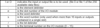
In addition to addressing physical I/O locations, virtual outputs can be addressed by specifying a slot number that is beyond the range of the number of slots that have defined modules located in the rack. As an example, the address O:10/0 would denote a virtual output whose data is stored in the 11th element in the output data file. This is a virtual output if no output module was defined to exist in slot 10 of the I/O rack.
How do you store/read variables using this addressing scheme?
In addition to I/O addressing, data files containing variables/values are also referenced using file based addressing. The B3 bit (or binary) file is used to store single bit status values (0 or 1). The N7 integer file is used to store integer values, and the F8 float file is used to store floating point values. Variables can be stored to, or read from these data file locations for use in PLC programs. Each of these 3 default file types (B3, N7, and F8) can employ files 9 through 255 should additional storage of a given type be required. For example, you can use B22, N37, and F145 as user specified data files should your application demand additional storage for these variable types. Remember, only the first 9 files of the available 256 data files are pre-defined and considered to be default. The remaining files can be specified to be any of the available file types.
The B3 Bit File:
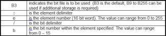
The B3 file is organised into a table containing 256 elements, each of which is 16 bits in length giving the user the ability to reference a total of 4096 bits per data file of the “B” type. Each bit in an element (16 bit word) is accessible using the file based addressing scheme. This file is ideal for setting and monitoring user defined status flags when desired application conditions exist. There are two ways in which the status of a given bit in this file can be specified. You can reference the element (word 0 - 255) in the table and then specify the bit within that element (bit 0 – 15). Alternately, you can also leave the element designation out of the address, and directly specify the bit number (bit 0 – 4096) in the data file table.
B3 Bit File Addressing Format:
Using Elements B3 : e / b
Where:
Using only bits B3 / b
Where:
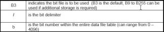
In summary, a status bit in the B3 data file table can be referenced in either one of two ways. If we want to address bit 3 in the 2nd element in the B3 data file, we can specify this memory location as B3:1/3 or we can alternately specify this memory location as B3/19. For ease of use, it is generally recommended that you use the element designation format as it allows for an additional layer of categorization when organizing status flag bits.
The N7 Integer File:
The N7 integer file is also organized into a table of 256 elements, each of 16 bit length. This file table allows for specifying elements as well as bits within an element, however, values stored to or read from this data file are typically values as opposed to single bit states. The addressing format is similar to the one used with the B3 file addressing that includes the element number.
N7 Integer File Addressing Format:
Integer File Addressing N7 : e / b
Where:
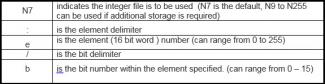
As an example, to store or read a value from the 4th element in this data file table, you would use the address N7:3 to identify the specific memory location for that integer value. Again, in general usage, you would not often have the need to specify a particular bit within the stored integer value.
The F8 Float File:
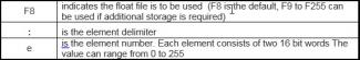
The F8 file is used to store or read floating point variables/values in memory. This file organization differs slightly from the ones described above for the B3 and N7 data files. Each file of this type contains 256 elements, however, in this case, each element is comprised of 2 words each being 16 bits in length. This means that consequently, this file type can be 2 times the size of a “B” or “N” type file. Another difference with this file type is that individual bits within elements cannot be individually referenced. Only elements inside this file type can be specified. This type of data file is ideal for storing and retrieving values used with math instructions and calculations. The basic format for the file based addressing scheme associated with this file type is similar to the ones previously outlined with the above noted exceptions.
F8 Float File Addressing Format:
Float File Addressing F8 : e
Where:
Floating point information can only be used by instructions that accept the REAL data type. Not all basic instructions can be used with floating point values stored in this data file table.
How do you reference information contained in data files specifically intended for use with instruction set items?
So far, we have covered addressing schemes that deal with data files that store information regarding physical I/O as well as variables that are used with PLC program. In addition to these types of data files, we will now take a look at some of the data file types used with the instructions that are available in the instruction set for the 500 series of AB controllers. There are 3 data file types which are intended for use with specific instructions. The T4 data file is used for storing timer variables and status bits. The C5 data file is used to store values relating to counter variables and status bits, and lastly the R6 data file is used to store information and status bits for “control items. (this last category would include sequencers, the FIFO and LIFO data stack instructions, as well as bit shift instructions among others. Each of these 3 data file types consists of 256 elements, each of which is comprised of three 16 bit words making these the largest of the data file types. We will move on now, to take a brief look at the addressing format for each of these data file types.
The T4 Timer File
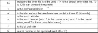
This file consists of 256 elements used to track the preset and accumulated values as well as the state of various status bits associated with timer operation. Each element in this file contains three 16 bit words. Word 0 in an element is referred to as the control word. It contains the status bits associated with the timer instruction (ie EN, TT, DN bits). Word 1 in an element is used to store the desired PRESET value for the timer. The last word in each element, Word 2 contains the ACCUMULATED value. (Note, the timers “time base” value is not addressable and cannot be specified using the file based addressing scheme).
T4 Timer File Addressing Format:
Timer Addressing T4 : e .s / b
Where:
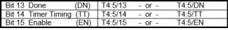
Addressable Bits in the Control Word (word 0) of a timing element:
When addressing word 0, you can leave out the word designation and simply reference the bit number for the desired status bit. It is also significant to note that you can use letters to denote specific bits in the control word. (ie EN, TT, and DN) These can be used to replace the numeric values denoting specific bits in the address. This means there are two ways to reference items in the control word (word 0) of a timer element. In the examples and explanation below, we are assuming that we are addressing the 6th element in the timer data file (Timer T4:5 would be the general reference for this timer in a program)
Addressable Words in a timing element (Word 1 and Word 2)
Word 1 of a timer element holds the preset value. This value can be referenced in one of two ways. You can include the word number, 1, or you can use the letters PRE to denote the storage location of the preset value, both of which are interpreted as equivalent references to word 1 of the timer element. This same approach can be used to designate word 2 in the element. This word contains the accumulated value. You can specify word 2, or you can use the letters ACC to denote the location of the accumulated value in the element.

In either instance of the above, (for both PRE and ACC addresses) you can add a designation specifying the particular bit inside either of these words in the element. For example, if we want to reference the least significant bit (bit 0) of the accumulated value of the 6th timer element in the table, we can do so as follows:

In summary, the status as well as preset and accumulated values can all be referenced down to the single bit level. The timer elements each contain three 16 bit words that are addressable using the file based addressing scheme. Individual bits inside each of these words can be referenced as well as then entire word in the case of the Preset and Accumulated values (word 1 and 2 in the element). In addition, there are several standard letter combinations that can be used in place of specific bit or word numbers. These letters provide easily identifiable references and it is recommended that they be used in place of the more obscure number only approach.
The C5 Counter File
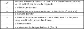
This file consists of 256 elements used to track the preset and accumulated values as well as the state of various status bits associated with counter operation. The address formatting for this data file is very similar to that employed for timers. The first word in the element, word 0 is the control word that contains the status bits associated with the counter function. The second word, word 1 is used to hold the preset value for the counter, and the last word in the element, word 2, is used to hold the accumulated value. As with the timer addressing scheme, certain letters can be used in place of bit or word numbers. The counter control word has several more addressable bits than the timer control word.
C5 Counter File Addressing Format:
Counter Addressing C5 : e .s / b
Where:
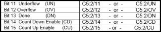
Addressable Bits in the Control Word (word 0) of a counter element
As with timer data files, counter data files use word 0 as the control word which contains the counter status bits. Here again, because we are addressing the first word in the element, the word designation part of the address can be omitted as it is not required. In addition, as with the timer data file, the counter data file addressing scheme recognizes specific letters that are used to denote bit numbers for particular status bits. In the examples and explanations below, we will be assuming that we are addressing the 3rd element ( C5:2 would be the reference to this counter in a program) for the purpose of illustration.
Addressable Words in Counter Element (Word 1 and Word 2)
Word 1 of a counter element holds the preset value. The same approach (using PRE instead of the word number) can be used with counters as was used with timers. This also applies to the use of ACC to denote word 2 of a counter element.

In either instance of the above, (for both PRE and ACC addresses) you can add a designation specifying the particular bit inside either of these words in the element. For example, if we want to reference the least significant bit (bit 0) of the accumulated value of the 3rd counter element in the table, we can do so as follows:

In summary, the counter data file type contains 256 elements, each of which is made up of three 16 bit words. These elements and the subsequent addressing scheme follow the same format laid out for the timer (T4) data file type. The only significant difference pertains to the control word bits that are addressable, and the letters used to denote them.
The R6 Control Data File
This file consists of 256 elements used to track the status, length of a bit array or file, and position pointer within an array information relating to instructions that employ this file type. Unlike the T4 and C5 data file types, this file type is used with several types of instructions. For this reason, there are many more status bits that are addressable in the control word (word 0) of each element in this data file. Various instructions use specific combinations of these control status bits. Not all status bits in the control word are used in each instruction type that employs this file to store information pertaining to the instructions operation.
R6 Control Data File Addressing Format:
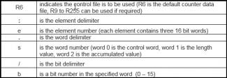
Control Data Addressing R6 : e .s / b
Where:
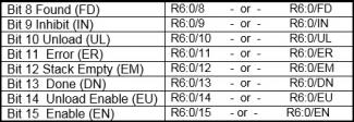
Addressable Bits in the Control Word (word 0) of a Control Data Element
As with timer and counter data files, control data files use word 0 as the control word which contains the control data status bits. As with our other multi word elements, because we are addressing the first word in the element for the status bits, the word designation part of the address can be omitted as it is not required. In addition, as with the timer and counter data file, the control data file addressing scheme recognizes specific letters that are used to denote bit numbers for particular status bits. In the examples and explanations below, we will be assuming that we are addressing the 1st element for the purpose of illustration. (R6:0 would be the reference used with an instruction employing the Control Data file type)
Addressable Words in Control Data Elements (Word 1 and Word 2)
Word 1 of a control data element holds the length of the bit array or file. Word 2 holds the position pointer location within that array. As with our previous multi word elements, we can reference these locations using the word number, (1 or 2) and also using LEN for length, and POS for position.

Once again, in either instance of the above, (for both LEN and POS addresses) you can add a designation specifying the particular bit inside either of these words in the element. For example, if we want to reference the least significant bit (bit 0) of the length value or the position value of the 1st control data element in the table, we can do so as follows:

To summarize, Control Data files are used with several instructions. This data file type uses elements consisting of three 16 bit words. As with the timer and counter data files, the first word, word 0, is used to store status bits used for the specific instructions that are employing the data file
Wrapping Up The Basics of File Based Addressing
In conclusion, the file based addressing scheme can be used to store, reference, and retrieve information pertaining to physical I/O locations, variables and values, as well as parameters relating to specific instruction set items used in PLC programs. The data file section of memory consists of 256 files. The first 9 files are of pre-determined types. The balance of the data files available (files 9 through 255) can be defined and used as any of the allowable data file types. Each data file type contains 256 elements that can be addressed individually. Depending on the data file type, and element can consist of 1, 2, or 3 distinct 16 bit words. In most cases, each word, as well as each bit in the word can be selectively addressed depending of the file type, and/or instruction it is being used with. There is a general consistency employed throughout the various data file types used by the file based addressing scheme and most aspects are common among the various data file types. We have examined 8 of the 9 default data files provided with the 500 series AB controllers. The data files that employ three word elements all allow for pneumonic referencing in lui of specifying bit or word numbers. The letters used for these are specific to the element and function they are being used with.
If you like this post, check out File Based Addressing Tips Part I.
We hope that this has been helpful as a student or practicing PLC technician. We are looking for other ideas for the Practicing PLC Technician Series. Please let us know if you have any ideas that you would like to see and send your thoughts to [email protected]