Discrete vs. Analog I/O: What's the Difference?
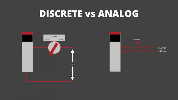
When it comes to learning the foundations of PLC programming, it can be as easy as flicking on and off a switch. That’s the main difference between discrete and analog I/O modules! Discrete signals are simply on or off, whereas analog signals vary.
PLCs are responsible for collecting data from input signals and sending the information through output signals to control devices in order to perform specific functions. Depending on the application or device, a PLC programmer must determine whether to use discrete or analog I/O.
When learning the fundamentals of PLC programming, it’s necessary to have a basic understanding of inputs and outputs, and the key differences between discrete and analog I/O modules. Keep reading to gain a deeper understanding of these two mechanisms.
Overview of Input and Output Communication
If you’re brand new to PLC training, I/O is a widely used term amongst technicians which stands for “Input/Output.” I/O is the communication between an information processing system and the outside world. Inputs are the signals, or data, received by the system and outputs are the signals sent from it.
One of the simplest ways to think of I/O is by using your computer as an example. Your computer is an information processing system, and the user is “the outside world.” Computer inputs would be the keyboard and mouse which receive commands from the user, whereas the outputs would be the monitor and printer. When you think of it in terms of a PLC, you should note that PLC’s are composed of two basic sections: the Central Processing Unit (CPU) and the I/O interface system. The I/O is what connects the information processing system (the CPU) to the outside world, like the machines and Human Machine Interface (HMI). Input modules detect the status of input signals, such as push buttons, switches and sensors. The output modules control devices such as motors, relays, and lights.
Discrete Input/Output Module PLC
Now that we’ve covered the basic information with regards to input and output signals, let’s get into the differences between discrete and analog systems.
Also called “digital I/O,” discrete I/O modules in PLCs refer to data when it is in one of two states: on or off. The signals are also referred to as 1 and 0, or open and closed. Discrete I/Os are typically far more simple than analog I/Os when learning PLC programming. An example of a discrete I/O would be a push-button switch, which turns a motor off and on with the use of pressure. Proximity switches are also an example of discrete I/O, as they can detect the presence of an object without physical contact, turning off or on without the use of force. A PLC becomes aware of a discrete sensor’s state when it receives a signal from a discrete input channel. Inside a discrete input module are typically a set of light-emitting diodes (LEDs) which become energized when the device is turned on. A photosensitive device turns on when it senses the LED, which activates inside the PLC’s memory.
The PLC then sends this information to control devices through a discrete output channel. Similarly, the PLC sends an LED signal which activates a photosensitive device. When sent through the PLC’s computer circuitry, these electrical power loads allow the control devices, such as a motor starter or indicator lamp, to function.
Analog Input/Output Module PLC
Analog I/O refers to signals with a range of values greater than 1 or 0, and are not simply on/off or open/closed. It typically measures voltage or current from the input, and supplies it to the output. Because analog I/O refers to ranges rather than one of two states, it’s a bit more complicated to learn for PLC programmers in training, especially if you’re new.
Analog input examples include temperature sensors, oil pressure sensors, CO2 sensors, and weight scales. Outputs would be used to control the power, current, or voltage sent to these sensors. Unlike discrete input modules which only use binary numbers “0” and “1,” analog input modules usually measure analog inputs in one of the following forms: -10 to 10 VDC, 0 – 10 VDC, 1 to 5 VDC, 0 to 1 mA, or 4 – 20 mA. In order for the PLC to understand the analog signals, they must be converted through an A/D converter or an analog to digital converter.
The analog outputs work similarly to discrete outputs, with the PLC sending the signal to the control devices such as control valves or variable frequency drives controlled by the PLC. An analog signal that is most common in our homes, and is a great example for newer PLC programmers, would be the dimmer switch. The dimmer switch can increase and decrease in small increments, allowing light to filter through the bulb; making it more complex than a simple on and off switch.
Learn It All With PLC Programming
PLCs collect and send data to and from input and output signals in order to control various operations within an industrial setting. Depending on the application or device, the PLC programmer is responsible for creating either a discrete or analog I/O module. Discrete and analog I/O are widely used in PLC programming, therefore it’s important for PLC Technicians to learn how to work with both.
If you’re interested in discrete and analog I/O modules and want a hands-on learning experience, consider applying for the PLC Technician Training Online Education Program.
Very educative