Everything You Wanted To Know About PLCs But Were Afraid To Ask
According to Markets Insider the industrial automation market is expected to have a 20% increase by 2024, exceeding USD $5 billion. With the ongoing rise and rapid growth in the automation and manufacturing industry, it’s no wonder that employers are looking for skilled technicians to stay on-trend in the industry. Today, Programmable Logic Controllers (PLCs) are an integral part of automation and manufacturing, and in order to be able to repair, maintain, and program those systems you will need the right training. The online based PLC Technician certificate program from George Brown College provides you with both the proper training and knowledge that you will require in order to work with PLC systems.
What is a PLC?
Let’s backup a bit to review what PLCs are and how they are used in our everyday lives. A programmable controller, or Programmable Logic Controller (PLC) is a device which is capable of being programmed to perform a controlling function of other devices. A PLC continuously monitors the state of input devices and makes logic-based decisions based on the user created programs to control the state of output devices. Elevators are an example of a mechanical system being controlled by a PLC. There is a defined program running in the PLC that detects the floor being requested and moves the elevator to the requested floor, most elevators are programmed and controlled by PLCs to take the most optimized route through any pending button calls and make their directional decision based on that.
Programmable controller devices are easy to install and program. Most PLCs are provided with quick- release type screw connections for fast wiring of input and output devices. PLC editing features allow program changes, corrections, and loading procedures to be accomplished in a matter of seconds in most cases. PLC systems are modular which means one can mix and match input and output devices as required.
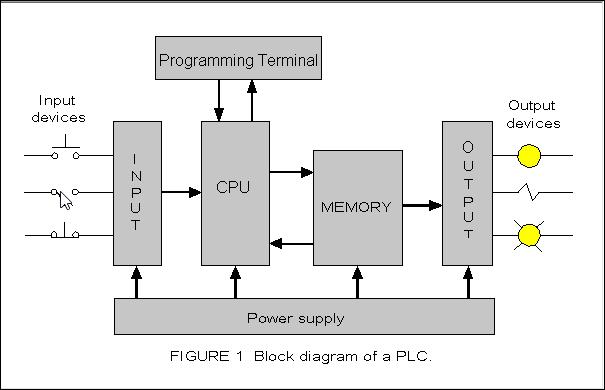
All programmable controllers have input and output interfaces, memory, a method of programming, a central processing unit (CPU), and a power supply. These functions are shown in Figure 1 - Functional block diagram of a PLC.
Where & how are PLC systems used?
PLC systems are very common and are found everywhere including manufacturing, food and service industries such as packaging, car wash, elevator, traffic lights, batch mixing, etc. For example, here is a video of a batch mixing application replicated within PLCLogix 5000, the simulation software included in our PLC Technician II Certificate program.
The world of PLCs is closer than you think. Please visit our blog, PLC Applications in our Everyday Lives to find out more about different PLC applications.
PLC Operation
There are four basic steps in the operation of all PLCs:
1. Input scan
PLC first examines all the input devices that are connected and store this information in the memory.
2. Program scan
PLC then scans the user created application program and executes the instructions based on this information.
3. Communications and internal diagnostics
Once the PLC is finished scanning the programming instructions, it then performs the internal diagnostic functions and communication tasks such as communicating with programming terminals, etc.
4. Output scan
At the end, PLC updates (energize/de-energize) the outputs and begins the cycle again.
Programming Language used to program a PLC
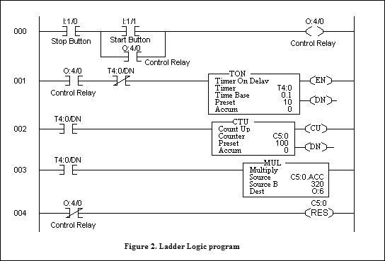
A PLC program is written by a user and is stored in the PLC's memory to produce the correct output control signals for a given process. PLC programming uses its own language. Like all languages, the language of a PLC has grammar, syntax, and vocabulary that allow the user to write a program stating what the CPU is required to do. Each PLC manufacturer use a slightly different programming language to do this. The programming language used to program PLCs is ladder logic which is an advanced form of relay logic. Ladder logic represents a program by a graphical diagram based on the circuit diagrams of relay logic hardware. Ladder logic includes specifying contact closure types and coils, programs allow entry of math functions, analog control, complex counter and timer operations, and so on. An example of a ladder logic program is shown in Figure 2 below.
Future of PLC
We are entering the world of automation, everything around us is either already automated or will become automated in near future. Automation is everywhere around us from driverless cars, automated trains at the airport; to the construction sites. Programmable Logic Controllers (PLCs) are an integral part of automation and is used in variety of industrial automation applications. “Automation” is the future and studying PLC will help to keep yourself updated.
How PLC Simulation tools can help you become a more successful PLC Technician
PLC Technicians design, program, repair and maintain programmable logic controller (PLC) systems. To become a successful PLC Technician, it is necessary to have extensive experience in programming, testing and de-bugging ladder logic programs. This experience can be achieved by working with PLC simulation software like PLCLogix.
PLCLogix simulation software is designed to emulate the operation of the most popular, Allen Bradley (AB) programmable logic controllers (PLCs), the Logix 500 and the Logix 5000. PLCLogix enables users to develop and practice their programming skills by converting their computer into a fully functioning simulated PLC to program, test and de-bug ladder logic programs.
PLCs are very expensive, and if programmed incorrectly, can result in lost manufacturing productivity and dangerous conditions. PLCLogix simulation software is very popular among PLC Technicians. It provides much needed “hands-on” experience as it allows one to write a program, see the program’s operation using a ladder logic simulator, and control the operation of the program using its interactive virtual environments.
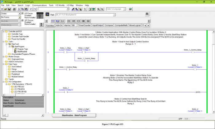
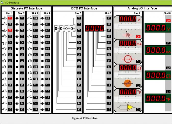
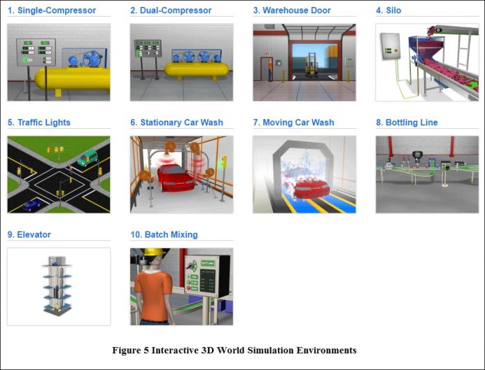
The Graphical User Interface (GUI) for PLCLogix has the same features and functionality as Allen Bradley RSLogix and it provides practical experience in the operation software of RSLogix and ControlLogix along with providing realistic 3D-World simulation environments. The purpose of the GUI is to provide a range of information displayed on a single screen. This information ranges from bit display to program code to status indicators. The PLCLogix GUI, I/O interface and 3D world environments are shown below in Figure 3, Figure 4 and Figure 5 respectively. PLCLogix also includes a free-form ladder editor that allows one to modify multiple rungs of logic at the same time. The point-and-click graphical interface provides a simple and realistic method of entering and editing ladder logic programs. (Visit our YouTube channel to see PLCLogix 5000 and PLCLogix 500 simulation software demonstration)
Gaining the proper PLC training will help you stay on-trend in the rapidly growing industry of automation and manufacturing. The PLC Technician and PLC Technician II certificate programs at George Brown College provides a complete examination of PLCs, covering theory, practical applications and PLC programming. The program is designed to be self-paced and easy-to-use, along with having an interactive curriculum, simulation software, student support and online examples providing a completely flexible learning framework that allows you to complete the program on your own terms. For more information please visit www.gbctechtraining.com or call our support center toll-free at 1-888-553-5333 to speak with a program consultant.
This blog does a great job of breaking down PLC concepts in a clear and approachable way—especially helpful for beginners trying to understand the role of PLCs in automation. I particularly appreciated the section on ladder logic and how it ties into real-world applications. Looking forward to more technical deep dives like this!