Basic Instructions and Operation of a PLC - Part 1
In this installment of the Practicing PLC Technician series, we are going to look at the basic structure of a PLC and how it operates.
In general, a PLC takes stimulus from the outside world and brings it into a computing environment. Decision or monitoring instructions within the PLC process the input information and instruct the outputs of the PLC to react to the stimulus in a determined manner. Field devices bring status information to the PLC, the program interprets the information and will then discern the appropriate actions or output to provide in response to the given input conditions. The adoption of PLC’s has resulted in the replacement of the majority of Relay Control Logic which has been historically used to control applications.
What are the basic components of a PLC?
In addition to the Input and Output rack locations, which most PLC technicians are familiar with, a PLC contains isolation circuitry, a CPU, data and address busses, memory storage, a power supply, and usually some kind of external MMI or man machine interface or terminal for programming. The number of types of input and output modules will vary according to the needs of the application for which the PLC is being employed.
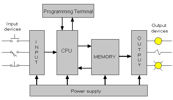
Above, we have a functional diagram representing the major components of a PLC system. The input and output devices can allow for a range of voltages or currents, and can be digital or analog in nature. The specifics of the I/O are largely dependent on the type of control application being performed. The actual PLC contains several sections not detailed in the block diagram including facilities for communications.
What is A Scan Cycle?
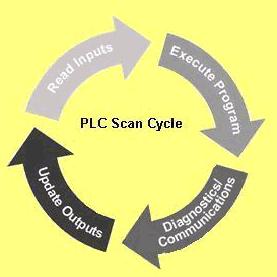
Generally, PLC’s operate by repeating what is called a “Scan Cycle”. This cycle consists of four basic functions. First, the inputs are read, next the program instructions are executed after which diagnostics and any required communications occurs, and finally, the outputs are updated. One important aspect of the scan cycle is the “Scan Time”. This is the total time it takes for the PLC to perform a complete scan cycle. This time can be critical in applications that require real time monitoring and control.
How are PLC’s Programmed?
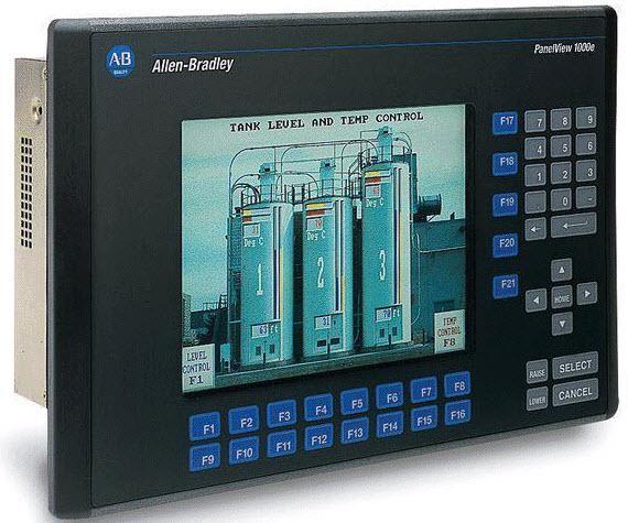
A programming terminal is used to input or edit a program and allows the program to be uploaded from the PLC to the terminal where it can be edited, or downloaded to a PLC where it can be run. These terminals can be PC computers, or simple dedicated HMI interfaces such as the one shown here.
There are several types of languages or approaches used for programming PLCs. These include Structured Text, Instruction Lists, Function Block Diagraming, as well as Ladder Logic programming. For the benefit of those technicians who have no programming experience, we will be working with the ladder logic programming approach in our discussions going forward. It uses a format that would be the most familiar for technicians who work with electronics and industrial control equipment. This programming language is based on relay logic as was used traditionally for industrial control applications so many aspects of it will be familiar to those technicians who have been working in the field.
Why Ladder Logic Programming?
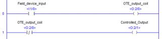
The primary reason ladder logic programming exists is that it allows technicians to easily interpret a PLC’s program by rendering the program in a format very familiar to technicians who have worked with relay logic controls prior to the advent and wide adoption of PLC’s. This programming language is very intuitive for those familiar with electrical wiring and relay control circuits and is easy to learn. Many technicians have worked with relays in the past. The physical device contains a coil, and one or more contacts that will change state depending on whether the coil is energized or not. This type of device is modelled in ladder logic programming by a OTE instruction, (serving as the coil) and one or more NO or NC contacts that are controlled by the coil.
Over the next few articles, we will further examine some instructions that are based on real life equipment or devices that are familiar to technicians already, that have been included in the ladder logic programming approach available for programming PLC’s. Items such as Time Delay Relays, Drum Sequencers, Counters, and Shift Registers are all recreated in virtual form for use in programming the PLC. We will be examining the Basics Of PLC Programming using some of the instructions that have real world counterparts that are traditionally familiar to technicians in the field.
If you like this post check out our other blogs in this series;
File Based Addressing Tips Part I
File Based Addressing Tips Part II
We hope that this has been helpful as a student or Practicing PLC Technician. We are looking for other ideas for this series. Please let us know if you have any ideas or would like to see and send your thoughts to [email protected].